PARTS AND MATERIALS
- Two 6 volt batteries
- One capacitor, 0.1 µF, non-polarized (Radio Shack catalog # 272-135)
- One 555 timer IC (Radio Shack catalog # 276-1723)
- Two light-emitting diodes (Radio Shack catalog # 276-026 or equivalent)
- One 1 MΩ resistor
- One 100 kΩ resistor
- Two 510 Ω resistors
- Audio detector with headphones
- Oscilloscope (recommended, but not necessary)
A oscilloscope would be useful in analyzing the waveforms produced by this circuit, but it is not essential. An audio detector is a very useful piece of test equipment for this experiment, especially if you don't have an oscilloscope.
CROSS-REFERENCES
Lessons In Electric Circuits, Volume 4, chapter 10: "Multivibrators"
LEARNING OBJECTIVES
- How to use the 555 timer as an astable multivibrator
- Working knowledge of duty cycle
SCHEMATIC DIAGRAM

ILLUSTRATION

INSTRUCTIONS
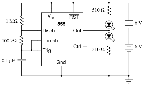
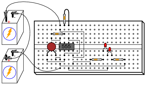
The "555" integrated circuit is a general-purpose timer useful for a variety of functions. In this experiment, we explore its use as an astable multivibrator, or oscillator. Connected to a capacitor and two resistors as shown, it will oscillate freely, driving the LEDs on and off with a square-wave output voltage.
This circuit works on the principle of alternately charging and discharging a capacitor. The 555 begins to discharge the capacitor by grounding the Disch terminal when the voltage detected by the Thresh terminal exceeds 2/3 the power supply voltage (Vcc). It stops discharging the capacitor when the voltage detected by the Trig terminal falls below 1/3 the power supply voltage. Thus, when both Thresh and Trig terminals are connected to the capacitor's positive terminal, the capacitor voltage will cycle between 1/3 and 2/3 power supply voltage in a "sawtooth" pattern.
During the charging cycle, the capacitor receives charging current through the series combination of the 1 MΩ and 100 kΩ resistors. As soon as the Disch terminal on the 555 timer goes to ground potential (a transistor inside the 555 connected between that terminal and ground turns on), the capacitor's discharging current only has to go through the 100 kΩ resistor. The result is an RC time constant that is much longer for charging than for discharging, resulting in a charging time greatly exceeding the discharging time.
The 555's Out terminal produces a square-wave voltage signal that is "high" (nearly Vcc) when the capacitor is charging, and "low" (nearly 0 volts) when the capacitor is discharging. This alternating high/low voltage signal drives the two LEDs in opposite modes: when one is on, the other will be off. Because the capacitor's charging and discharging times are unequal, the "high" and "low" times of the output's square-wave waveform will be unequal as well. This can be seen in the relative brightness of the two LEDs: one will be much brighter than the other, because it is on for a longer period of time during each cycle.
The equality or inequality between "high" and "low" times of a square wave is expressed as that wave's duty cycle. A square wave with a 50% duty cycle is perfectly symmetrical: its "high" time is precisely equal to its "low" time. A square wave that is "high" 10% of the time and "low" 90% of the time is said to have a 10% duty cycle. In this circuit, the output waveform has a "high" time exceeding the "low" time, resulting in a duty cycle greater than 50%.
Use the audio detector (or an oscilloscope) to investigate the different voltage waveforms produced by this circuit. Try different resistor values and/or capacitor values to see what effects they have on output frequency or charge/discharge times.

No comments:
Post a Comment
Please give valuable comments on this post.