
So far, the filter designs we've concentrated on have employed either capacitors or inductors, but never both at the same time. We should know by now that combinations of L and C will tend to resonate, and this property can be exploited in designing band-pass and band-stop filter circuits.
Series LC circuits give minimum impedance at resonance, while parallel LC (“tank”) circuits give maximum impedance at their resonant frequency. Knowing this, we have two basic strategies for designing either band-pass or band-stop filters.
For band-pass filters, the two basic resonant strategies are this: series LC to pass a signal (Figure below), or parallel LC (Figure below) to short a signal. The two schemes will be contrasted and simulated here:
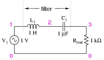
Series resonant LC band-pass filter.
Series LC components pass signal at resonance, and block signals of any other frequencies from getting to the load. (Figure below)
series resonant bandpass filter
v1 1 0 ac 1 sin
l1 1 2 1
c1 2 3 1u
rload 3 0 1k
.ac lin 20 50 250
.plot ac v(3)
.end

Series resonant band-pass filter: voltage peaks at resonant frequency of 159.15 Hz.
A couple of points to note: see how there is virtually no signal attenuation within the “pass band” (the range of frequencies near the load voltage peak), unlike the band-pass filters made from capacitors or inductors alone. Also, since this filter works on the principle of series LC resonance, the resonant frequency of which is unaffected by circuit resistance, the value of the load resistor will not skew the peak frequency. However, different values for the load resistor will change the “steepness” of the Bode plot (the “selectivity” of the filter).
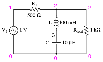
The other basic style of resonant band-pass filters employs a tank circuit (parallel LC combination) to short out signals too high or too low in frequency from getting to the load: (Figure below)

Parallel resonant band-pass filter.
The tank circuit will have a lot of impedance at resonance, allowing the signal to get to the load with minimal attenuation. Under or over resonant frequency, however, the tank circuit will have a low impedance, shorting out the signal and dropping most of it across series resistor R1. (Figure below)
parallel resonant bandpass filter
v1 1 0 ac 1 sin
r1 1 2 500
l1 2 0 100m
c1 2 0 10u
rload 2 0 1k
.ac lin 20 50 250
.plot ac v(2)
.end

Parallel resonant filter: voltage peaks a resonant frequency of 159.15 Hz.
Just like the low-pass and high-pass filter designs relying on a series resistance and a parallel “shorting” component to attenuate unwanted frequencies, this resonant circuit can never provide full input (source) voltage to the load. That series resistance will always be dropping some amount of voltage so long as there is a load resistance connected to the output of the filter.
It should be noted that this form of band-pass filter circuit is very popular in analog radio tuning circuitry, for selecting a particular radio frequency from the multitudes of frequencies available from the antenna. In most analog radio tuner circuits, the rotating dial for station selection moves a variable capacitor in a tank circuit.

Variable capacitor tunes radio receiver tank circuit to select one out of many broadcast stations.
The variable capacitor and air-core inductor shown in Figure above photograph of a simple radio comprise the main elements in the tank circuit filter used to discriminate one radio station's signal from another.
Just as we can use series and parallel LC resonant circuits to pass only those frequencies within a certain range, we can also use them to block frequencies within a certain range, creating a band-stop filter. Again, we have two major strategies to follow in doing this, to use either series or parallel resonance. First, we'll look at the series variety: (Figure below)
Series resonant band-stop filter.
When the series LC combination reaches resonance, its very low impedance shorts out the signal, dropping it across resistor R1 and preventing its passage on to the load. (Figure below)
series resonant bandstop filter
v1 1 0 ac 1 sin
r1 1 2 500
l1 2 3 100m
c1 3 0 10u
rload 2 0 1k
.ac lin 20 70 230
.plot ac v(2)
.end

Series resonant band-stop filter: Notch frequency = LC resonant frequency (159.15 Hz).
Next, we will examine the parallel resonant band-stop filter: (Figure below)

Parallel resonant band-stop filter.
The parallel LC components present a high impedance at resonant frequency, thereby blocking the signal from the load at that frequency. Conversely, it passes signals to the load at any other frequencies. (Figure below)
parallel resonant bandstop filter
v1 1 0 ac 1 sin
l1 1 2 100m
c1 1 2 10u
rload 2 0 1k
.ac lin 20 100 200
.plot ac v(2)
.end

Parallel resonant band-stop filter: Notch frequency = LC resonant frequency (159.15 Hz).
Once again, notice how the absence of a series resistor makes for minimum attenuation for all the desired (passed) signals. The amplitude at the notch frequency, on the other hand, is very low. In other words, this is a very “selective” filter.
In all these resonant filter designs, the selectivity depends greatly upon the “purity” of the inductance and capacitance used. If there is any stray resistance (especially likely in the inductor), this will diminish the filter's ability to finely discriminate frequencies, as well as introduce antiresonant effects that will skew the peak/notch frequency.
A word of caution to those designing low-pass and high-pass filters is in order at this point. After assessing the standard RC and LR low-pass and high-pass filter designs, it might occur to a student that a better, more effective design of low-pass or high-pass filter might be realized by combining capacitive and inductive elements together like Figure below.

Capacitive Inductive low-pass filter.
The inductors should block any high frequencies, while the capacitor should short out any high frequencies as well, both working together to allow only low frequency signals to reach the load.
At first, this seems to be a good strategy, and eliminates the need for a series resistance. However, the more insightful student will recognize that any combination of capacitors and inductors together in a circuit is likely to cause resonant effects to happen at a certain frequency. Resonance, as we have seen before, can cause strange things to happen. Let's plot a SPICE analysis and see what happens over a wide frequency range: (Figure below)
lc lowpass filter
v1 1 0 ac 1 sin
l1 1 2 100m
c1 2 0 1u
l2 2 3 100m
rload 3 0 1k
.ac lin 20 100 1k
.plot ac v(3)
.end

Unexpected response of L-C low-pass filter.
What was supposed to be a low-pass filter turns out to be a band-pass filter with a peak somewhere around 526 Hz! The capacitance and inductance in this filter circuit are attaining resonance at that point, creating a large voltage drop around C1, which is seen at the load, regardless of L2's attenuating influence. The output voltage to the load at this point actually exceeds the input (source) voltage! A little more reflection reveals that if L1 and C2 are at resonance, they will impose a very heavy (very low impedance) load on the AC source, which might not be good either. We'll run the same analysis again, only this time plotting C1's voltage, vm(2) in Figure below, and the source current, I(v1), along with load voltage, vm(3):

Current inceases at the unwanted resonance of the L-C low-pass filter.
Sure enough, we see the voltage across C1 and the source current spiking to a high point at the same frequency where the load voltage is maximum. If we were expecting this filter to provide a simple low-pass function, we might be disappointed by the results.
The problem is that an L-C filter has a input impedance and an output impedance which must be matched. The voltage source impedance must match the input impedance of the filter, and the filter output impedance must be matched by “rload” for a flat response. The input and output impedance is given by the square root of (L/C).
Z = (L/C)1/2
Taking the component values from (Figure below), we can find the impedance of the filter, and the required , Rg and Rload to match it.
                For L= 100 mH,   C= 1µF
         Z = (L/C)1/2=((100 mH)/(1 µF))1/2 = 316 Ω
In Figure below we have added Rg = 316 Ω to the generator, and changed the load Rload from 1000 Ω to 316 Ω. Note that if we needed to drive a 1000 Ω load, the L/C ratio could have been adjusted to match that resistance.
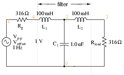
Circuit of source and load matched L-C low-pass filter.
LC matched lowpass filter
V1 1 0 ac 1 SIN
Rg 1 4 316
L1 4 2 100m
C1 2 0 1.0u
L2 2 3 100m
Rload 3 0 316
.ac lin 20 100 1k
.plot ac v(3)
.end
Figure below shows the “flat” response of the L-C low pass filter when the source and load impedance match the filter input and output impedances.

The response of impedance matched L-C low-pass filter is nearly flat up to the cut-off frequency.
The point to make in comparing the response of the unmatched filter (Figure above) to the matched filter (Figure above) is that variable load on the filter produces a considerable change in voltage. This property is directly applicable to L-C filtered power supplies– the regulation is poor. The power supply voltage changes with a change in load. This is undesirable.
This poor load regulation can be mitigated by a swinging choke. This is a choke, inductor, designed to saturate when a large DC current passes through it. By saturate, we mean that the DC current creates a “too” high level of flux in the magnetic core, so that the AC component of current cannot vary the flux. Since induction is proportional to dΦ/dt, the inductance is decreased by the heavy DC current. The decrease in inductance decreases reactance XL. Decreasing reactance, reduces the voltage drop across the inductor; thus, increasing the voltage at the filter output. This improves the voltage regulation with respect to variable loads.
Despite the unintended resonance, low-pass filters made up of capacitors and inductors are frequently used as final stages in AC/DC power supplies to filter the unwanted AC “ripple” voltage out of the DC converted from AC. Why is this, if this particular filter design possesses a potentially troublesome resonant point?
The answer lies in the selection of filter component sizes and the frequencies encountered from an AC/DC converter (rectifier). What we're trying to do in an AC/DC power supply filter is separate DC voltage from a small amount of relatively high-frequency AC voltage. The filter inductors and capacitors are generally quite large (several Henrys for the inductors and thousands of µF for the capacitors is typical), making the filter's resonant frequency very, very low. DC of course, has a “frequency” of zero, so there's no way it can make an LC circuit resonate. The ripple voltage, on the other hand, is a non-sinusoidal AC voltage consisting of a fundamental frequency at least twice the frequency of the converted AC voltage, with harmonics many times that in addition. For plug-in-the-wall power supplies running on 60 Hz AC power (60 Hz United States; 50 Hz in Europe), the lowest frequency the filter will ever see is 120 Hz (100 Hz in Europe), which is well above its resonant point. Therefore, the potentially troublesome resonant point in a such a filter is completely avoided.
The following SPICE analysis calculates the voltage output (AC and DC) for such a filter, with series DC and AC (120 Hz) voltage sources providing a rough approximation of the mixed-frequency output of an AC/DC converter.
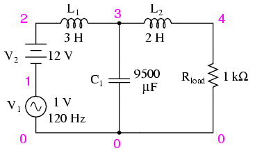
AC/DC power suppply filter provides “ripple free” DC power.
ac/dc power supply filter
v1 1 0 ac 1 sin
v2 2 1 dc
l1 2 3 3
c1 3 0 9500u
l2 3 4 2
rload 4 0 1k
.dc v2 12 12 1
.ac lin 1 120 120
.print dc v(4)
.print ac v(4)
.end
v2            v(4)
1.200E+01     1.200E+01   DC voltage at load = 12 volts

freq          v(4)
1.200E+02     3.412E-05   AC voltage at load = 34.12 microvolts
With a full 12 volts DC at the load and only 34.12 µV of AC left from the 1 volt AC source imposed across the load, this circuit design proves itself to be a very effective power supply filter.
The lesson learned here about resonant effects also applies to the design of high-pass filters using both capacitors and inductors. So long as the desired and undesired frequencies are well to either side of the resonant point, the filter will work OK. But if any signal of significant magnitude close to the resonant frequency is applied to the input of the filter, strange things will happen!
- REVIEW:
- Resonant combinations of capacitance and inductance can be employed to create very effective band-pass and band-stop filters without the need for added resistance in a circuit that would diminish the passage of desired frequencies.
-


No comments:
Post a Comment
Please give valuable comments on this post.